line test
cloce line
Tuesday, September 10, 2013
Monday, September 9, 2013
POWER DIODES
To understand how a power diode works, we need to describe a few things. This has
NEVER been described before, so read carefully.
The 240v AC (called the "mains") consists of two wires, one is called the ACTIVE and
the other is NEUTRAL. Suppose you touch both wires. You will get a shock. The neutral
is connected to an earth wire (or rod driven into the ground or connected to a water
pipe) at the point where the electricity enters the premises and you do not get a shock
from the NEUTRAL.
DAMPER DIODES
A damper diode is a diode that detects a high voltage and SQUELCHES IT (reduces it -
removes it). The signal that it squelches is a voltage that is in the opposite direction to
the "supply voltage" and is produced by the collapsing of a magnetic field. Whenever a
magnetic filed collapses, it produces a voltage in the winding that is opposite to the
supply voltage and can be much higher. This is the principle of a flyback circuit or EHT
circuit. The high voltage comes from the transformer.
The diode is placed so that the signal passes through it and less than 0.5v appears
across it.
A damper diode can be placed across the coil of a relay, incorporated into a transistor
or FET or placed across a winding of a flyback transformer to protect the driving
transistor or FET.
It can also be called a "Reverse-Voltage Protection Diode," "Spike Suppression Diode,"
or "Voltage Clamp Diode."
The main characteristic of a Damper Diode is HIGH SPEED so it can detect the spike
and absorb the energy.
It does not have to be a high-voltage diode as the high voltage in the circuit is being
absorbed by the diode.
SCHOTTKY DIODES SILICON, GERMANIUM
SILICON, GERMANIUM AND SCHOTTKY DIODES
When testing a diode with an analogue meter, you will get a low reading in one
direction and a high (or NO READING) in the other direction. When reading in the LOW
direction, the needle will swing nearly full scale and the reading is not a resistancevalue
but a reflection of the characteristic voltage drop across the junction of the
diode. As we mentioned before, a resistance reading is really a voltage reading and the
meter is measuring the voltage of the battery minus the voltage-drop across the
diode.
Since Silicon, Germanium and Schottky Diodes have slightly different characteristic
voltage drops across the junction, you will get a slightly different reading on the scale.
This does not represent one diode being better than the other or capable of handling a
higher current or any other feature.
The quickest, easiest and cheapest way to find, fix and solve a problem caused by a
faulty diode is to replace it.
There is no piece of test equipment capable of testing a diode fully, and the circuit you
are working on is actually the best piece of test equipment as it is identifying the fault
UNDER LOAD.
Only very simple tests can be done with a multimeter and it is best to check a diode
with an ANALOGUE MULTIMETER as it outputs a higher current though the diode and
produces a more-reliable result.
A Digital meter can produce false readings as it does not apply enough current to
activate the junction.
Fortunately almost every digital multimeter has a diode test mode. Using this, a
silicon diode should read a voltage drop between 0.5v to 0.8v in the forward direction
and open in the reverse direction. For a germanium diode, the reading will be lower,
around 0.2v - 0.4v in the forward direction. A bad diode will read zero volts in both
directions.
LIGHT EMITTING DIODES (LEDs)
Light Emitting Diodes (LEDs) are diodes that produce light when current flows from
anode to cathode. The LED does not emit light when it is revered-biased. It is used as
a low current indicator in many types of consumer and industrial equipment, such as
monitors, TV’s, printers, hi-fi systems, machinery and control panels.
The light produced by a LED can be visible, such as red, green, yellow or white. It can
also be invisible and these LEDs are called Infrared LEDs. They are used in remote
controls and to see if they are working, you need to point a digital camera at the LED
and view the picture on the camera screen.
An LED needs about 2v - 3.6v across its leads to make it emit light, but this voltage
must be exact for the type and colour of the LED. The simplest way to deliver the
exact voltage is to have a supply that is higher than needed and include a voltagedropping
resistor. The value of the resistor must be selected so the current is between
2mA and 25mA.
The cathode of the LED is identified by a flat on the side of the LED. The life
expectancy of a LED is about 100,000 hours. LEDs rarely fail but they are very
sensitive to heat and they must be soldered and de-soldered quickly. They are one of
the most heat-sensitive components.
Light emitting diodes cannot be tested with most multimeters because the
characteristic voltage across them is higher than the voltage of the battery in the
meter.
However a simple tester can be made by joining 3 cells together with a 220R resistor
and 2 alligator clips:
LED TESTER
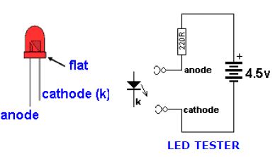
Connect the clips to a LED and it will illuminate in only one direction.
The colour of the LED will determine the voltage across it. You can measure this
voltage if you want to match two or more LEDs for identical operation.
Red LEDs are generally 1.7v to 1.9v. - depending on the quality such as "high-bright"
Green LEDs are 1.9v to 2.3v.
Orange LEDs are about 2.3v and
White LEDs and IR LEDs are about 3.3v to 3.6v.
The illumination produced by a LED is determined by the quality of the crystal. It is the
crystal that produces the colour and you need to replace a LED with the same quality
to achieve the same illumination.
Never connect a LED across a battery (such as 6v or 9v), as it will be instantly
damaged. You must have a resistor in series with the LED to limit the current.
anode to cathode. The LED does not emit light when it is revered-biased. It is used as
a low current indicator in many types of consumer and industrial equipment, such as
monitors, TV’s, printers, hi-fi systems, machinery and control panels.
The light produced by a LED can be visible, such as red, green, yellow or white. It can
also be invisible and these LEDs are called Infrared LEDs. They are used in remote
controls and to see if they are working, you need to point a digital camera at the LED
and view the picture on the camera screen.
An LED needs about 2v - 3.6v across its leads to make it emit light, but this voltage
must be exact for the type and colour of the LED. The simplest way to deliver the
exact voltage is to have a supply that is higher than needed and include a voltagedropping
resistor. The value of the resistor must be selected so the current is between
2mA and 25mA.
The cathode of the LED is identified by a flat on the side of the LED. The life
expectancy of a LED is about 100,000 hours. LEDs rarely fail but they are very
sensitive to heat and they must be soldered and de-soldered quickly. They are one of
the most heat-sensitive components.
Light emitting diodes cannot be tested with most multimeters because the
characteristic voltage across them is higher than the voltage of the battery in the
meter.
However a simple tester can be made by joining 3 cells together with a 220R resistor
and 2 alligator clips:
LED TESTER
Connect the clips to a LED and it will illuminate in only one direction.
The colour of the LED will determine the voltage across it. You can measure this
voltage if you want to match two or more LEDs for identical operation.
Red LEDs are generally 1.7v to 1.9v. - depending on the quality such as "high-bright"
Green LEDs are 1.9v to 2.3v.
Orange LEDs are about 2.3v and
White LEDs and IR LEDs are about 3.3v to 3.6v.
The illumination produced by a LED is determined by the quality of the crystal. It is the
crystal that produces the colour and you need to replace a LED with the same quality
to achieve the same illumination.
Never connect a LED across a battery (such as 6v or 9v), as it will be instantly
damaged. You must have a resistor in series with the LED to limit the current.
ZENER DIODE TESTER
ZENER DIODES
All diodes are Zener diodes. For instance a 1N4148 is a 120v zener diode as this is its
reverse breakdown voltage.
And a zener diode can be used as an ordinary diode in a circuit with a voltage that is
below the zener value.
For instance, 20v zener diodes can be used in a 12v power supply as the voltage never
reaches 20v, and the zener characteristic is never reached.
Most diodes have a reverse breakdown voltage above 100v, while most zeners are
below 70v. A 24v zener can be created by using two 12v zeners in series and a normal
diode has a characteristic voltage of 0.7v. This can be used to increase the voltage of a
zener diode by 0.7v. See the diagram above. It uses 3 ordinary diodes to increase the
output voltage of a 3-terminal regulator by 2.1v.
To tests a zener diode you need a power supply about 10v higher than the zener of the
diode. Connect the zener across the supply with a 1k to 4k7 resistor and measure the
voltage across the diode. If it measures less than 1v, reverse the zener.
If the reading is high or low in both directions, the zener is damaged.
Here is a zener diode tester. The circuit will test up to 56v zeners.

ZENER DIODE TESTER
All diodes are Zener diodes. For instance a 1N4148 is a 120v zener diode as this is its
reverse breakdown voltage.
And a zener diode can be used as an ordinary diode in a circuit with a voltage that is
below the zener value.
For instance, 20v zener diodes can be used in a 12v power supply as the voltage never
reaches 20v, and the zener characteristic is never reached.
Most diodes have a reverse breakdown voltage above 100v, while most zeners are
below 70v. A 24v zener can be created by using two 12v zeners in series and a normal
diode has a characteristic voltage of 0.7v. This can be used to increase the voltage of a
zener diode by 0.7v. See the diagram above. It uses 3 ordinary diodes to increase the
output voltage of a 3-terminal regulator by 2.1v.
To tests a zener diode you need a power supply about 10v higher than the zener of the
diode. Connect the zener across the supply with a 1k to 4k7 resistor and measure the
voltage across the diode. If it measures less than 1v, reverse the zener.
If the reading is high or low in both directions, the zener is damaged.
Here is a zener diode tester. The circuit will test up to 56v zeners.
ZENER DIODE TESTER
Friday, September 6, 2013
පරිගණකය ස්ලෝ ද? සොෆට්වයා නොදා සරල ක්රම මගින් වෙගවත් කරමු.

- ටෙම්පරි ෆයිල් එකතු වී තිබීම
- හාඩ් එකේ මෙහෙයුම් පද්දතියට අදාල ෆයිල් අපිලිවෙලට තිබීම
- ස්ටාටප් වැඩසටහන් අනවශ්ය ලෙස ධාවනය වීම
- වයිරස් ආසාදන
- හාඩ් වයා වලට දැරිය නොහැකි os එකක් දමා තිබීම
- අනවශ්ය වැඩසටහන් දමා තිබීම
- හාඩ් වයා දෝෂ හා නොගැලපීම් (ඉතිරිය කියවන්න)
Subscribe to:
Posts (Atom)